But wait... don't those tubes require a letal high anode voltage and a big transformer for heating? True for most, but not for mine. I found some miniature tubes that work perfectly with the organ's 24V power supply, they need only a few milliamps for heating. How that?
Let the Russians do the work!
Remember russian pilot Victor Belenko who defected to Japan in his MIG-25 Foxbat fighter back in 1976? U.S. military officials were stunned when they examined what they thought was the most advanced fighter jet in the world. The Russians, it turned out, were still using old-fashioned vacuum tubes instead of state-of-the-art transistors and computer chips. For all their vaunted military reputation, the Soviets seemed incredibly backward. Eventually though, it dawned on the Americans that the Soviets had figured out the old tubes would be less vulnerable to the electro-magnetic pulse of a nuclear blast than some newer components. The MIG-25 fighter was equipped with thousands of miniature vacuum tubes, and most of them are still available, since the russians literally made millions of them for military stock. Data of these tubes is pretty hard to find on the web, because the cyrillic transcription of their numbering is not consistent. Kindly people here in Europe have collected them, and some can be found at Elektronikinfo or at Franz Hambergers R÷hrentabellen. Any preconceptions against russian quality? Look: These tube were designed to work in a combat fighter even at a nuclear bomp drop. Or ask an audiophool for the reputation of the russian 6C33 power triode, the one which was used in the MIG's power supply.
|
|
|
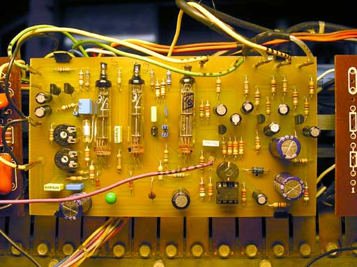
Left picture above shows the pre-productional prototype of my MIG-T preamp. The tube in the middle of the PCB (type 1SH29b or 1J29b) is the preamp output stage, the two tubes to the left (type 1SH24b or 1J24b) work as the additional overdrive stage. The IC to the right is a LM2574ADJ "Simple Switcher", a high-efficiency switching power supply circuit which produces the 1,2V DC for heating. The transistorized preamp stages (upper right side) are fitted with low-noise transistors and straight frequency response. The two transistors to the left work as emitter-follower to adapt the tubes' high output impedance to the output. Bias is chosen to drive the preamp output tube slightly in distortion, which is of very "sweet" type and adds a nice warm tone. The additional overdrive stage adds a compression and a soft symmetrical clipping, all with that vintage "thump". Overdrive gain and output volume is settable by the trimpots on the left. Two jumpers between the tube stages define the amount of key click by different high frequency responses. You may use either the clean output or the overdriven output (choose by a obsolete tab switch, by example).
The MIG-T preamp simply rocks - download the MIG-T tube preamp MP3 sound example (clean and overdriven, played on a plain T-500 with all my published modifications, solely through internal leslie unit and internal speakers). I apologize for the quality of the performance - I'm a technician, not a skilled player!
Installation instructions
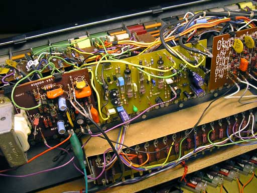
The MIG-T comes ready built and is pretty easy to install. Please read Skill 1 to 3 to disassemble the organ and to remove the original transistor preamp board 124-000014. Write down the wire numbers and tag the wires. The MIG-T pinning (see MIG-T circuit schematics - actual circuit might be changed without notice) has the same order and numbering scheme as the Hammond board, with two excemptions: First, power supply is routed from the red +24V wire of the adjacent vibrato preamp board (left board on pictures, see green alligator clip on right picture). The filtered +21V supply (former yellow wire to pin P1) is not capable of the heater current required for the tubes. Cut the yellow wire or tug it away. Second, it has two outputs (upper overdrive, lower clean) which may be routed to a switch for choosing the clean or overdriven sound on the fly. The trimpots adjust clean level (upper) and drive (lower). Adjust to personal taste and a warm, not too harsh sound. The two jumpers set the frequency response. For an non-recalibrated tone generator, you have to install both, leaving one or both open yields more treble and more key click. Please see the MIG-T instructions PDF for latest changes and complete documentation including parts layout.
I decided to design a PCB for it and sell it in pre-build kit form. Email me if you want one (built and tested) or use the paypal order form below. It costs 119 EURO plus shipping (8.20 EURO in Europe, 4.30 Euro in Germany). You may obtain additional kits (plain PCB with tubes and parts, soldering required) also.
SORRY, SOLD OUT -- VERY FEW LEFT OVER. EMAIL ME FOR A QUOTE
If you own a Leslie, use the MIG-L instead.
Want to buy one? See my ebay shop for actual pricing and availability. Thank you for supporting my web page by ordering a MIG-T board!
Generator Recalibration
Using the MIG-T might require a generator recalibration if you find your organ to be too aggressive or shrill.
Bright Organ
- Recalibrate the tone generator's higher notes from tone number 48 up to 91 (see T-Series magnet locations) to a reading around 4 mV RMS (10 mV pp on an oscillocope) on the terminal strip. You will need a 4 mm hexnut driver for the small screws holding the magnetic rods and a RMS millivoltmeter (analog meter is easier to read). The corresponding note on the manual must be played (pressed) when adjusting the level, otherwise you will get too high readings, especially on the higher notes (see manual wiring chart for key-to-tone correspondence). Alternatively instead of playing the notes you may use a 27 Ohm shunt resistor across the input terminals of the millivoltmeter as a load to the pickup coils. Be carefull to adjust the right coil when reading the Millivoltmeter -- the frequencies are not consecutive! Pushing the rod too far into the generator to get higher output may seriously damage the corresponding tonewheel. Rusted rods may be loosened by tapping with a screwdriver's handle. Do not use a hammer since this may demagnetize the rods. Pull the rod (slightly!) until you reach the appropriate reading.
- When you had modified the busbar preamps by removing the Miller caps, instead of looking up the notes on the terminal strip you may check the tone output voltage at Pin 5 of the recovery preamp board 124-000014 while playing the appropriate note with a single drawbar pulled (upper manual, no percussion, vibrato off). See what the average reference level is by playing single lower notes on 8' drawbar (might be a little higher than generator output, a few millivolts). Set higher notes accordingly by adjusting the rods like mentioned above. For the uppermost tones use the 2' drawbar. So you don't have to worry about the numbering on the terminal strip, just for the magnet locations. I used a small hammer to depress the note on the manual while adjusting the rod and observing the voltmeter.
Smooth Organ
- You'll get a smoother M100-like sound with more "bottom" click when decreasing ("tapering") the reading from tone number 48 and up. I found the following values to be optimal for my organs (values are not critical, but should tend to the specified voltage):
| up to 47 |
5.0 mV Reference level, leave unchanged |
|
48 to 60 |
4.2 mV (was 5 to 6 mV) or leave unchanged if nearby |
| 61 to 72 |
3.5 mV (was 7 mV) |
| 73 to 85 |
3.0 mV (was 9 mV) |
| 86 to 91 |
2.8 mV (was 10 to 12 mV) |
- For exact values like my best sounding organs and easier location of notes on the terminal strip, get my T-Series Generator Calibration Excel spreadsheet (to be unzipped) and measure voltages (given in mV RMS and using a 27 Ohm shunt resistor as mentioned above) directly on the generator terminal strip. Rows in this spreadsheet are arranged that they represent the terminal strip tone order from left to right.
The Lazy Way
- Some people say it's easier to install a shunt resistor (parallel from generator tone terminal to ground) instead of readjusting the rod to get the proper value. You may try resistors in the range 6.8 Ohms to 47 Ohms.