I have no idea why Hammond makes their 70's spinett organs sound like cheesy home organs. No click, dull sound, cheesy bottom. First we want to recover the key click and get a better base sound. This first modification is very easy. Even if you are not technically skilled, you should give it a try. You need a working organ, some simple tools and minimal experience to do this. Grab a screwdriver, a cutting pliers and a small soldering iron.
- Remove back of organ. Remove 3 screws from underside the upper wood bar. You should be able to lift the top board at back of the organ a little. To the front the lid may be fastened in two ways, dependant of the year of manufacture:
- with two snap-in-bolts to the front switch panel which can be unfastened be simply pulling up in one go,
- OR it is attached to the side panels with two wooden dowels which slide into slots in the top lid. The lid should come up by moving it backwards or forwards, and the same time forcing it up.
- Remove metal cover from upper switch assembly. Locate the two bus amplifier boards, they are located behind the drawbar assembly. The drawbar wires are coded like resistor color rings, BTW: from brown = drawbar 1 (16' rank) to white = drawbar 9 (1' rank).
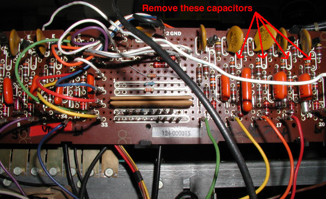
- Remove 4 Miller integrator filter capacitors for upper manual drawbar 1 (16') to drawbar 4 (4'), see arrows on picture above, parts numbered C238, C234, C 230, C226 marked red on upper bus amplifier PCB schematic and layout.
- Remove 2 Miller integrator filter capacitors for lower manual drawbar 8' and drawbar 4' (parts numbered C102, C106, similar location as above) marked red on lower bus amplifier PCB schematic and layout.
- You may want to remove the Rhythm III unit permanently if you have a T-500. Hammond suggests a substitution plug for the rhythm unit connector. Without this lower manual and pedals do not work. You may omit the 180 Ohm resistor without any drawback.